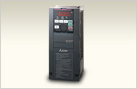
FR-A800 Plus series
Dedicated inverter for specialized fields FR-A800 Plus series.
The optimum functions for each dedicated field are added to the already high performance and high functionality of FR-A800 series inverter.
Enquiry about FR-A800 Plus series

Enter the security code shown above
FR-A800-CRN
Inverter with various functions ideal for a crane application such as reduction in tact time, load slippage prevention, etc.

Pursuing optimum functions to meet our customers’ needs
A new lineup of dedicated inverters for specialized fields are born!
Plus! The optimum functions for each dedicated field are added to the already high performance and high functionality FR-A800 series inverter.
Anti-sway control
By using the Mitsubishi Electric’s original anti-sway control technology, the swinging of an object moved by a crane is suppressed at the time of stopping, even without operator’s input adjustment.
This control cuts down the tact time and facilitates efficient operation.

Load torque high-speed frequency control (mode 2)
When there is a light-load (when light loads are moved up or down by a crane), the speed will automatically be increased. This reduces the tact time and facilitates efficient operation.
The possible operation speed is set automatically according to the load. After starting the inverter, the inverter runs at high speed with a light load.
Built-in brake transistor
22K inverters or lower in the 200 V class and 55K inverters or lower in the 400 V class have a built-in brake transistor.
Connecting a brake resistor*1 can shorten the deceleration time; no brake unit or power regeneration converter is required.
*1 The brake resistor must have a sufficient capacity to consume the regenerative power.
Shortest-time torque startup function
The time from the start command to when the brake opens is shortened. This will contributes to reduction in tact time.
- · Shortest-time torque startup function :
The optimum distribution of the excitation current and torque current enables rapid startup of the torque. - · Magnetic flux command during pre-excitation :
Decreasing the pre-excitation current during a motor stop reduces power consumption during standby, and enables rapid startup of the torque.

Load slippage prevention
Brake sequence function
The highly scalable brake sequence function enables the output of a brake opening signal for the optimum brake operation calculated from the load torque or the speed.
The function enables setting of the brake opening level individually for forward rotation and reverse rotation.
Low-speed range speed control P gain
When an inverter is connected to a lift, the inverter has a load immediately after the lift brake is released. Adjusting the speed control P gain in the low-speed range improves the response at low speed, and shortens the time from startup to brake opening.
Falling detection
Slippage during the start of a lift can be checked.
When the commanded direction differs from the actual motor rotation direction, the falling detection signal is output.

Dedicated monitoring functions
Overload detection function
By outputting an overload detection signal when too much load (overload) is applied to a crane, this information can be transmitted to the superordinate controller.
During constant speed operation, when the motor torque is equal to or higher than the torque setting for the time setting or longer, the overload detection signal is turned ON.
Start count monitor
The inverter starting times can be counted.
Confirming the starting times can be used to determinate the timing of the maintenance, or can be used as a reference for system inspection or parts replacement.

Wide range of applications
Compliance with ship classification standards
Using the recommended noise filter in combination with the inverter supports compliance with various countries ship classifications, such as NK, LR, DNV GL, ABS, BV, CCS, and KR.
The FR-A800-CRN can be used for electric deck cranes on ship.

FR-A800-R2R
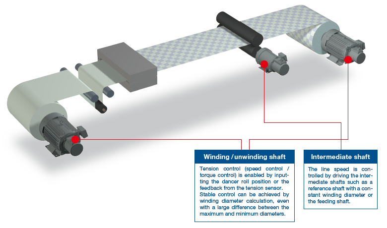
The FR-A800-R2R inverter has various dedicated functions such as winding diameter calculation, providing stable winding/unwinding control independently.

In roll to roll applications, control is necessary for machining of elongated products such as paper, film, and thread. Processing types include printing, slitting, coating, and twisting. High productivity can be achieved by stable tension control.
The FR-A800-R2R inverter can be used in a wide variety of systems with various dedicated functions.

- System simplification
Stable winding/unwinding can be achieved by the inverter alone. - Wide range of applications
The FR-A800-R2R inverter enables the use in various system applications such as winding/unwinding in the wire drawing machines and printers. - Easy startup and adjustment
Parameters can be used for mechanical adjustment according to applications.

System simplification
The FR-A800-R2R inverter has various dedicated functions such as winding diameter calculation, providing stable winding/unwinding control independently.
Winding diameter calculation
The present winding diameter for the winding/unwinding shaft is calculated from the actual line speed or the actual motor speed.
The line speed command and actual line speed required for calculating the winding diameter can be input through the analog input terminal or plug-in option.
The winding diameter calculation method can be selected in order to improve the tension control performance.
- ● Actual line speed calculation method
The winding diameter is calculated from the line speed and the main speed (actual motor speed).

- ● Thickness calculation method
The material thickness is added up to find the overall winding diameter.
D = Initial diameter ± 2 × d × N × Z

When the winding diameter changes after the material change or others, the present winding diameter is calculated in the following two ways.
- ● The present winding diameter is calculated based on the dancer roll movement at a start from the lower limit position to the target position.

- ● The present winding diameter is calculated from the line speed and the actual motor speed.
(The system must be started at low speed.)

Dancer feedback speed control / Tension sensor feedback speed control
PID control is performed using feedback of the detected dancer roll position or feedback from the tension sensor.
Stable control can be achieved in combination with the winding diameter calculation.
By adjusting the speed control proportional gain according to the winding diameter, the response level can be kept constant.
By automatically adjusting the tension PI gain for PID control, time required for adjustment is significantly cut down.
Anyone can start the system easily.

When material rupture (break) occurs and the sensor feedback value (dancer/tension feedback) is held at the upper/lower limit for a certain period of time, the break detection signal is output.

Tension sensorless torque control / Tension sensor feedback torque control
The output torque of a motor is controlled so that the tension applied to a material is constant by calculating the winding diameter of a roll.
The tension applied to the material is maintained constant by raising a commanded torque to compensate mechanical loss caused by factors such as friction on the dancer roll or winding/unwinding shaft.
During acceleration/deceleration, the tension applied to the material is maintained constant by adjusting the variable tension on the winding and unwinding sides.
By adjusting the tension on the workpiece, it is possible to avoid imperfections such as wrinkles or deformation caused by the increase in diameter.
The cushion time is set for the tension command to avoid sudden change in tension.


Related products
Computerized Numerical Controllers(CNCs)
High-voltage Alternating
Computerized Numerical Controllers(CNCs)
High-voltage Alternating
High-voltage Alternating
Energy Saving Supporting Devices
Controllers
Controllers


